Powering wireless medical instrumentation requires the right approach
Medical products must operate properly and switch seamlessly between a variety of power sources such as an AC mains outlet, battery backup and even harvested ambient energy sources. Furthermore, great lengths must be taken to protect against and tolerate faults, maximize operating time when powered from batteries and ensure that normal system operation is reliable whenever a valid power source is present.
One of the current key trends fueling growth in the potable and wireless medical instrumentation is patient care. Specifically, this is the increased use of remote monitoring systems within the patient’s own home. The key reason for this is trend is purely one of economics and that is the continuous increasing costs of keeping a patient in a hospital are simply too prohibitive. As a result, many of these portable electronic monitoring systems must incorporate RF transmitters so that any data gathered from the patient can be sent directly back to a supervisory system within the hospital for both immediate or later review and analysis by the governing physician.
Given this typical scenario, it is reasonable to assume that the cost of supplying the appropriate medical instrumentation to the patient for in-home use is more than offset by the cost of keeping the patient at the hospital of observation purposes. Nevertheless, it is of paramount importance that the equipment used by the patient be reliable and fool-proof. As a result, the manufactures and designers of such products must ensure that they can run seamlessly from multiple power sources while also ensuring the high reliability of their wireless data transmissions back to the hospital. This requires that the system designer takes great care when designing the power management architecture. It must be robust, flexible, compact and efficient.
Potential Pitfalls & Solutions
It is not unusual for a system designer to use linear regulators in a system that incorporates wireless transmission capability. The primary reason being that it minimizes EMI and noise emissions. Nevertheless, although switching regulators generate more noise than linear regulators, their efficiency is far superior. Noise and EMI levels have proven to be manageable in many sensitive applications as long as the switcher behaves predictably. If a switching regulator switches at a constant frequency in normal mode, and the switching edges are clean and predictable with no overshoot or high frequency ringing, then EMI is minimized. Moreover, a small package size and high operating frequency can provide a small tight layout, which minimizes EMI radiation. Furthermore, if the regulator can be used with low ESR ceramic capacitors, both input and output voltage ripple can be minimized, which are additional sources of noise in the system.
The main input power to today’s feature-rich medical devices is usually a 24V or 12V DC source from an external AC/DC adapter. This voltage it then further reduced to either 5V and/or 3.xV rails using synchronous buck converters. Nevertheless, the number of internal post-regulated power rails in these medical devices has increased while operating voltages have continued to decrease. Thus, many of these systems still require 3.xV, 2.xV or 1.xV rails for powering low power sensors, memory, microcontroller cores, I/O and logic circuitry. Furthermore, since the medical device operation is often critical, many of them often incorporate a battery back-up system to guarantee operation should the main power supply to the unit fail for some reason.
Traditionally, the lower voltage rails have been supplied by step-down switching regulators or low-dropout regulators. However, these types of ICs do not capitalize on the battery cell’s full operating range, thereby shortening the device’s potential battery run time. Therefore, when a buck-boost converter is used (it can step voltages up or down from a variable input source) it will allow the battery’s full operating range to be utilized. This increases the operating margin and extends the battery run time as more of the battery’s useful capacity is attained, especially as it nears the lower end of its discharge profile.
It is clear that a DC/DC converter solution that solves the primary cell system application requirements, as well as the associated issues already discussed, should have the following attributes:
- A buck-boost power conversion architecture with wide input voltage range to regulate the output voltage through a variety of battery-powered sources and their associated voltage ranges
- Ultralow quiescent current, both in operating mode and shutdown, to increase battery run time
- The ability to efficiently power system rails
- Capably count Coulombs accurately without significantly affecting IC quiescent current (battery consumption), to determine remaining battery state of charge
- Current limiting for attenuating inrush currents thus protecting the cells
- Small, lightweight and low profile solution footprints
- Advanced packaging for improved thermal performance and space efficiency
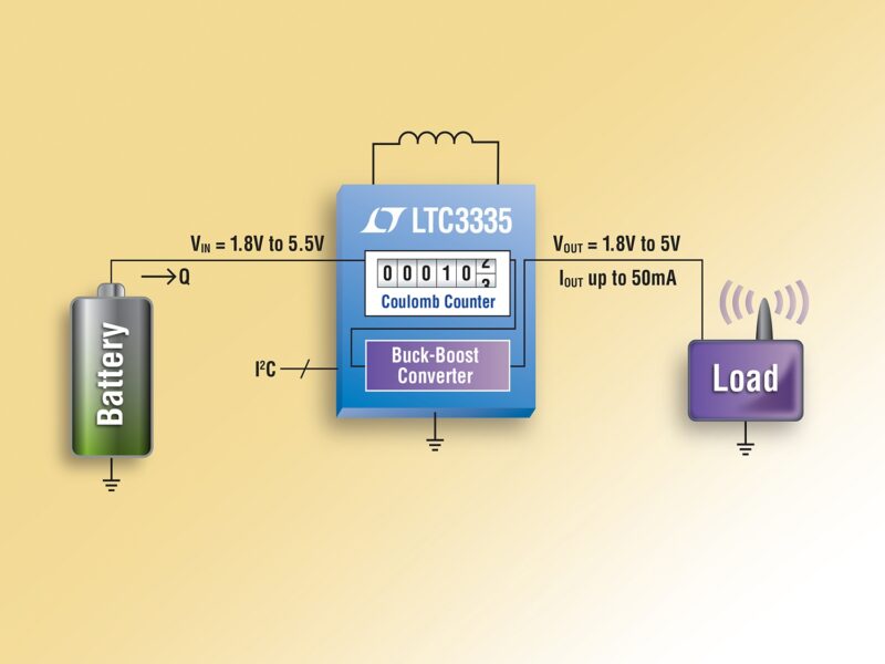
A recent product introduction from Linear Technology, the nanopower LTC3335 buck-boost converter with integrated Coulomb counter, has all of these attributes already. The device was designed for primary battery applications that need really low quiescent current and also need to know something about remaining battery capacity. Or, where potential battery component or load leakage may be detected by the coulomb counter as a check for system faults. See Figure 1.

The LTC3335 is a nanopower high efficiency synchronous buck-boost converter with an onboard precision Coulomb counter that delivers up to 50mA of continuous output current. With only 680nA of quiescent current and programmable peak input currents from as low as 5mA up to 250mA, the device is ideally suited for a wide variety of low power battery applications, such as those found in battery backed up portable health monitoring systems. Its 1.8V to 5.5V input range and 8 user-selectable outputs between 1.8V and 5V provide a regulated output supply with an input voltage above, below or equal to the output.
In addition, the device’s integrated precision (±5% battery discharge measurement accuracy) coulomb counter provides accurate monitoring of accumulated battery discharge in long-life non-rechargeable battery-powered applications which in many cases have extremely flat battery discharge curves. The LTC3335 includes four internal low RDSON MOSFETs and can deliver efficiencies of up to 90%. Other features include a programmable discharge alarm threshold, an I2C interface for accessing coulomb count and device programming, a Power Good output, and 8 selectable peak input currents from 5mA up to 250mA to accommodate a wide range of battery types and sizes. The LTC3335 is available with an operating junction temperature range from -40°C to +125°C in a thermally enhanced, 20-lead 3x4mm QFN package.
Another way to get a combination of low voltages rails from a DC input of 24V or 12V is to use a high voltage DC/DC converter with multiple output capabilities. Therefore, Linear Technology developed its 4 output monolithic synchronous buck converter, the LT8602. Its 3V to 42V input voltage range make it ideal for medical applications. As can be seen in Figure 2, its quad channel design combines two high voltage 2.5A and 1.5A channels with two lower voltage 1.8A channels to deliver four independent outputs delivering voltages as low as 0.8V, enabling it to drive the lowest voltage microprocessor cores currently available. Its synchronous rectification topology delivers up to 94% efficiency while Burst Mode® operation keeps quiescent current under 30µA (all channels on) in no-load standby conditions making it ideal for battery operated systems.

For noise-sensitive applications, the LT8602, with a small external filter, can utilize its pulse-skipping mode to minimize switching noise and can meet the CISPR25, Class 5 EMI requirements. This enables it to be used readily in systems that incorporate wireless transmission of data.
The LT8602’s switching frequency can be programmed from 250kHz to 2MHz and can be synchronized throughout this range. Its 60ns minimum on-time enables 16VIN to 2.0VOUT step-down conversions on the high voltage channels with a 2MHz switching frequency. As the high voltage VOUT2 channel feeds the two low voltage channels (VOUT3 and VOUT4), these can deliver outputs as low as 0.8V while also switching at 2MHz, offering a very compact (~25mm x 25mm single sided) quad output solution as shown in Figure 3.

In addition the minimizing the solution footprint, the LT8602’s 2MHz switching frequency enables designers to avoid critical noise-sensitive frequency bands. Each channel of the LT8602 maintains a minimum dropout voltage of only 200mV (at 1A) under all conditions, enabling it to excel in scenarios such as automotive cold-crank. Programmable power-on reset and power good indicators for each channel helps to ensure overall system reliability. The LT8602’s 40-lead thermally enhanced 6x6mm QFN package and high switching frequency keeps external inductors and capacitors small, providing a compact, thermally efficient footprint. In addition, unique design techniques and a new high speed process enable high efficiency over a wide input voltage range and the LT8602’s current-mode topology enables fast transient response and excellent loop stability.
Conclusion
It is clear that a system architect of wireless medical instrumentation faces many technical hurdles when designing a medical system for in-home patient care. The issue of potential noise interference must be mitigated, a battery backup operational capability in case the main power source fails and the size and cost have to be kept under control. Fortunately, there are plenty of appropriate solutions available from Linear to meet these design requirements.
About the author:
Tony Armstrong is Director of Product Marketing for Power Products at Linear Technology Corporation – www.linear.com
 If you enjoyed this article, you will like the following ones: don't miss them by subscribing to :